Experiment Overview
CaSSIS (Colour and Stereo Surface Imaging System), as its name suggests, is a high resolution imaging system designed to complement the data acquired by the other payload on EMTGO while also enhancing our knowledge of the surface of Mars by extending the observations of the High Resolution Imaging Science Experiment (HiRISE) which is currently orbiting Mars onboard NASA’s Mars Reconnaissance Orbiter (MRO).
The instrument comprises a number of sub-elements:
Telescope
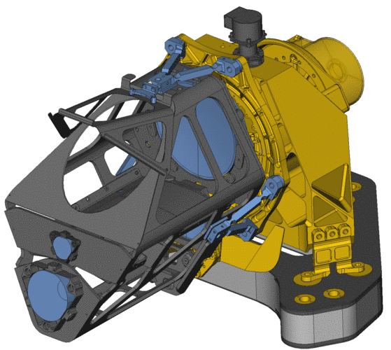
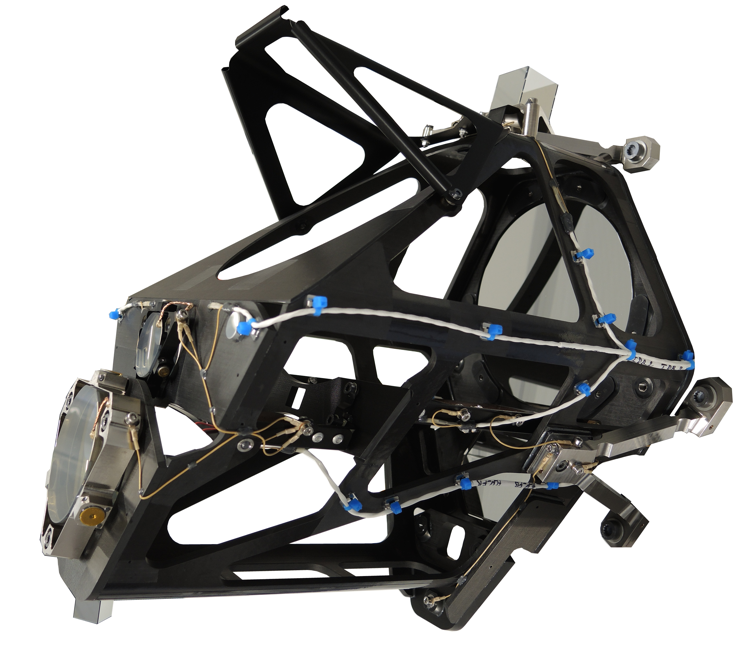
The CaSSIS telescope was originally conceived as a three-mirror anastigmat system (off-axis) with a fold mirror. The absence of a central obscuration reduces the straylight by allowing simplified baffling. However, the continuing delays with implementation have forced us to choose a solution with an already-existing mirror for the M1 component. The mother for this mirror has already been manufactured and a section of it identified for the CaSSIS M1. (It should be noted that otherwise manufacturing time for this mirror would normally be 14 months alone). The absence of development has also forced consideration of a non-lightweighted solution for M1 – which has the negative effect of forcing the instrument mass up.
A solution has been found using the pre-existing mirror for M1. This is not trivial because there is a need to force the detector behind M3 for integration purposes. The resulting optical design has power on all four reflecting surfaces.
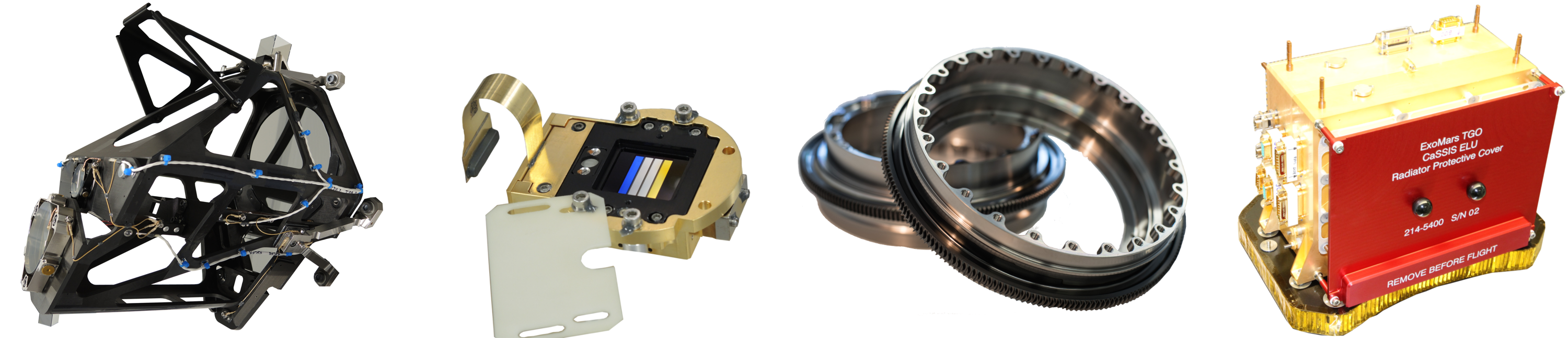
The primary mirror is around 13.5 cm in diameter. The mirrors are held in a carbon fiber reinforced polymer (CFRP) structure. The focal plane will comprise a single silicon hybrid detector with 4 colour filters mounted on it following the push-frame technique to be used by the SIMBIOSYS experiment onboard ESA’s BepiColombo.
Focal Plane System
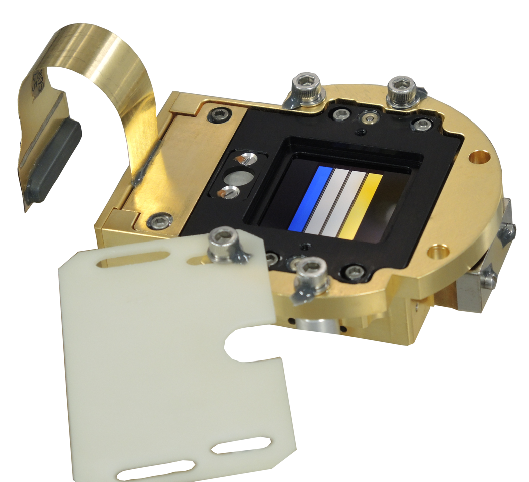
The system is based on re-use of the focal plane assembly of the SIMBIOSYS instrument for ESA’s BepiColombo mission. The system is based upon a Raytheon Osprey 2k hybrid CMOS detector. The detector can be read-out extremely quickly with 14 bit digital resolution. However, it remains a framing device meaning that acquiring an un-smeared image along a rapidly moving ground-track requires short exposures and a rapid imaging sequence. The along-track dimension of the image is then built up and put together on ground (see above).
To avoid mechanisms the detector is covered with a single monolithic rad-hard fused silica substrate with filters deposited on it. Different coatings with different transmission properties cover the substrate to produce the CaSSIS Filter Strip Assembly (FSA). The transmissions are relatively broad because of signal to noise considerations. Between the filters are small dark bands needed to reduce spectral cross-talk.
Rotation Mechanism
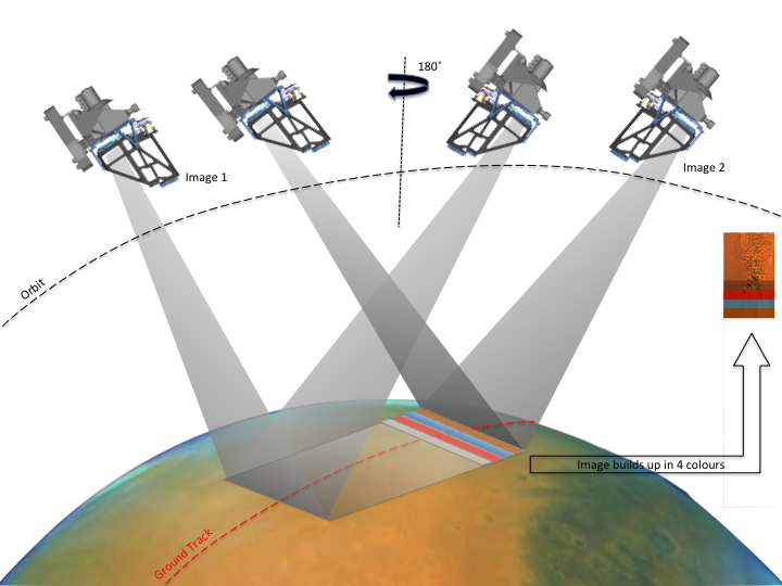
The telescope and focal plane are mounted on a rotation mechanism. This allows us to solve two key problems. Firstly, the rotation of the spacecraft about the nadir direction can be compensated for. Prior to image acquisition, the imager can be rotated. so that the lines are orthogonal to the direction of motion. (In case of rotation mechanism failure, the system would be able to acquire data but at reduced resolution and lower signal to noise.) Secondly, the rotation mechanism can be swiveled by ~180° to acquire a stereo image. Hence, the imager has been designed to look 10° ahead of the spacecraft for the first image and 10° behind to acquire the stereo pair. The time necessary to complete the rotation drives the design of the rotation mechanism.
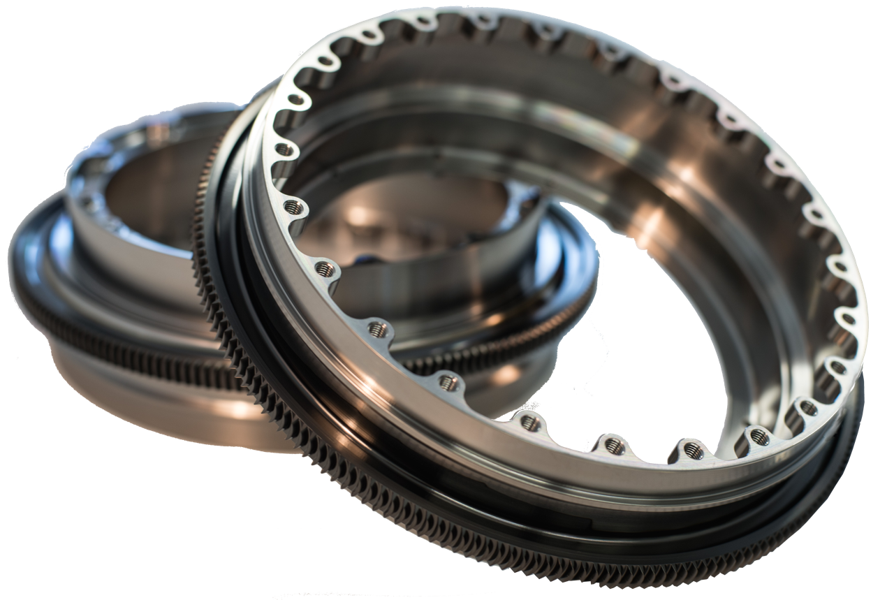
The rotation mechanism consists of a hollow shaft supported by two ceramic bearings and driven by a torus gear, whereby the torus wheel is integral part of the hollow shaft. The reduction ratio is ca. 200:1 (exact value depends on final design).
High-strength titanium alloys are used for the gear component, which are hard coated to provide durability. The housing is made of AlBeMet. A stepper motor (modified Port Escap P430) is connected to the torus shaft via a bellow coupling. End switches are used for zeroing; backlash is compensated by S/W and is calibrated in-flight.
A cable management system (the twist capsule) has been implemented to support cables which go from the rotating part of the instrument to fixed electronics box.
Electronics Unit
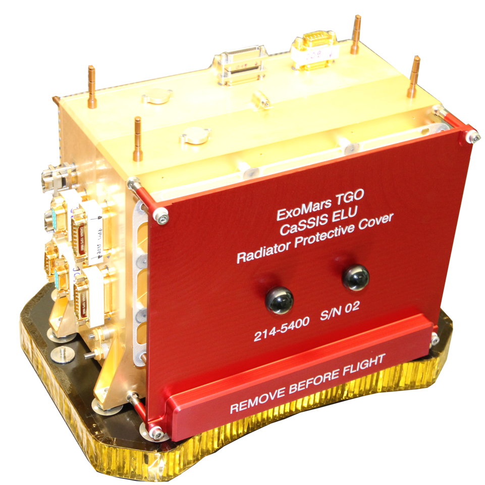
The ELU is the main command and telemetry interface between the instrument and spacecraft bus, supporting all instrument functions including imaging, rotation control, and instrument thermal control. The following image shows the ELU or E-Box from the side where all the connectors from the Spacecraft are connected.
The electronics unit comprises 3 modules which are assembled with board to board connectors to generate a complete box. The modules are:
- Power Converter Modules (PCM)
- Digital Processing Module (DPM)
- Rotation Control Module (RCM)
Parameters
| Quantity | Value |
|---|---|
| Orbit type | Circular |
| Orbit altitude | 400 km |
| Orbit inclination | 72 deg |
| Orbit period | 1.966 h |
| Mars radius | 3394 km |
| Mars eccentricity | 0.0934 |
| Perihelion dist. | 1.387 AU |
| Aphelion dist. | 1.666 AU |
| Mars density | 3.94 g/cm3 |
| Solar flux at periapsis | 718.9 W m-2 |
| Solar flux at apoapsis | 498.2 W m-2 |
| Maximum ground track speed | 3.012 km/s |
| Maximum change in true anomaly |
0.0509 deg/s |
| Focal length | 880 mm |
| Aperture diameter | 135 mm |
| Nominal F# |
6.52 |
| Pixel size (square) | 10 um |
| Angular scale | 11.36 urad /px |
| Scale at periapsis |
4.54 m/px |
| Scale at apoapsis | 4.54 m/px |
| Rotation axis-boresight angle | 10.0 +/- 0.2 deg |
| Stereo angle from 400 km altitude |
22.39 deg |
| Nominal slant distance to surface | 406.92 km |
| Scale at slant angle |
4.62 m/px |
| Time between stereo points along track | 46.91 s |
| Bits per pixel | 14 (returned as 2 byte integers) |
| Maximum dwell time (1 px of smear) | 1.51 ms |
| Detector size | 2048 x 2048 px |
| Image size | 2048 x 256 px |
| Number of images returned per exposure | 4 |
| Detector area used | 2048 x 1350 |
| FOV of used area | 1.33 deg x 0.88 deg |
| Nominal image overlap | 10% |
| Pixel read rate | 5 MHz |
| Time between exposures | 367 ms |
| Read-time of sub-images (all) | 419 ms |
| Filters (central wavelength/bandwidth) | |
| Pan | 675 nm / 250 nm |
| Blue-Green | 485 nm / 165 nm |
| Red | 840 nm / 100 nm |
| IR | 985 nm / 220 nm |